Fuel Valve Checks
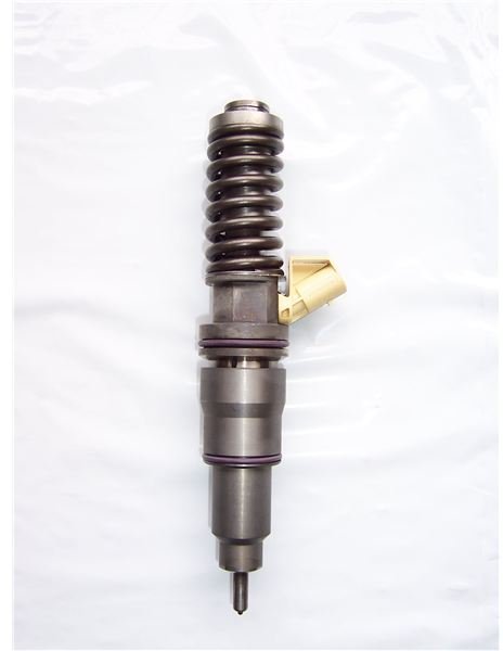
The fuel valves taken out from the engine must be checked for function and performance. Even in engines which are stopped on heavy fuel oil in ports the fuel injector taken out must be immediately tested with diesel oil before they get cold as this will flush and clean the components. It must be noted that if the fuel valves taken out are tested after they have cooled, will show bad performance even if they were performing satisfactorily in service.In the majority of cases the fuel injectors have a good spray profile but they open up at a less pressure. The pressure adjustment can be done without opening up the valve and should be done so. The engine manufacturers also instruct that unless the fuel injector valve has a major problem like holes choked or valve dripping, they should not be opened up. The valve should be cleaned from the outside, pressure checked, pressure adjusted and tagged.Inspection and Repairs
In the case where the fuel injector valve is not performing as required and has some defect, then it needs to be opened up and overhauled. The assembly and the disassembly have to be done as per the instructions given by the engine manufacturer. However, below is a general guide about what you will most likely have to do.After the fuel valve has been disassembled then the following checks have to be done:1. The needle guide should be immersed in clean diesel oil and the needle taken out and checked for free movement. In the case of any resistance which may be due to the presence of carbon or fuel sludge the needle may be put in and pulled out in succession many times while keeping it submerged in diesel oil. It is important to do this in a container full of clean diesel oil so the contaminants can be flushed away.2. After the needle guide has been cleaned, the needle should be taken almost out and then let it fall in with its own weight. A free and smooth movement with small jerks as the clearance is making way for the oil to come out is an indication that the clearances are all right and the needle guide is in good condition. It must be noted that the needle should fall fully into the seat.- 3. On the other hand if the needle falls fully in one go, then the clearances have increased and the fuel will leak past the spindle and less fuel will go in the cylinder. The needle must be inspected for any wear marks if this happens. The needle guide can be used but must be changed soon.4. If the needle does not go down and gets struck then it must be thoroughly cleaned again. If still there is no improvement then the needle might have become bent. Check the needle for any signs of overheating.
5. The push rod end should be checked for any abnormal wear.
6. The seating between the nozzle body and the valve body if damaged can be repaired by lapping with fine lapping paste. It must be noted that the lapping paste should be thoroughly flushed away with clean diesel oil and thereafter blown dry with compressed air.
7. Check the nozzle spring for breakage, poor seating and other defects. Change if required.
8. Check the leak off pipes, shims, packing etc for the condition. If the fuel valve is water cooled, the cooling pockets should be cleaned with compressed air. Tests and Adjustments
1. After the parts are cleaned and inspected the fuel valve is assembled as per the manufacturer’s instructions and thereafter tested for function and performance.2. The assembled fuel valve is installed on the test stand and after purging the pipe line the manual handle is operated in quick succession. The nozzle should start discharging with a sharp crackling noise at the set pressure. The pressure at which the injector is supposed to fire depends upon the manufacturer’s engine design but normally is between 250 to 350 kg/cm2 with an allowance of plus or minus 10 kg/cm2.3. In case the lifting pressure is not correct, it can be adjusted by the adjusting screw.4. The spray characteristics should be satisfactory and as per the manufacturers advice.5. All the holes of the injector should be firing and can be checked by a torch light or a filter paper can be folded as a cone and then the injector tested. The holes on the filter paper will show the number of holes firing. In this procedure you must be careful as the high pressure spray can enter the skin and is toxic for us.6. The spray angle should be as stated by the manufacturer. The atomization of the fuel should take place and solid spray should not come out.7. Clean diesel oil should be used for the testing purpose.8. In the case that the fuel valve is dripping the needle guide should be taken out and repaired.Caution
The needle and the guide is always a pair and should not be interchanged with another one. Cleanliness is the most important factor in making fuel valves. A clean fuel valve lasts a longer time. The fuel under pressure can enter the skin and the blood stream and is toxic for humans. Take care that you stay away from the spray. The fine mist can catch fire and in inflammable. Do not smoke or use naked lights where the fuel injectors are being tested.Image Credits
Friday, April 17, 2015
Test and Overhaul of Fuel Injection Valves of marine engines- Why diesel oil testing is usually done first??

Working of Electro magnetic brakes - Fail safe arrangement for Engine room cranes.

Basiclly, a lever which is connected to the arm which carries the brake shoes are pulled in when the circuit is denergized, it releases only when the circuit is energized and the drum will become free to move. Explained operation is given below. This is a fail safe arrangement as a power failure wil ensure the braes tighted on to the drum,
The Shoes are of cast iron and other components are of fabricated steel. The lever is hinged on the main arm, which is connected to the side arm through a tie rod, and is stressed by a pre-loaded compression spring. The compression of the spring can be adjusted to set the braking torque to desired value. The brake liner of selected quality material is riveted to the shoes by aluminum rivets. A.C. solenoid with laminated magnetic sheet steel houses a copper magnetizing coil which is impregnated with Class F materials. The plunger which is connected to the lever, is drawn in to the coil, when it is energized with AC source. This loads the spring and releases the brake shoes from the brake drum. When the supply is cut off, the plunger is pulled out of the coil, and spring force clamps the brake shoes on the brake drum and the brake is applied.
Usuallt this kind of brakes are used in E/R cranes, motors and other heavy rotating machineries which needed to be stopped instantlt, and needs to hold load.
Under voltage and over current trips
The Under Voltage trip stops you putting a generator that is not generating full voltage onto the board.
Checking of the trips:
I would always check the makers Instruction Manual for the specific breaker before trying to do anything.
As this is a procedure that is usually carried out for the Classification Society Special Survey of Electrical Equipment, and will usually be carried out by a specialist electrical contractor, often the licensed service agent for the Breaker Manufacturer. It would usually be carried out as part of the 5 yearly Special Survey during a drydock when the vessel would be on shore power.
No testing would normally be carried out with the Alternator running yet alone on load. The Breaker would have to be electrically isolated from the Generators and the Main Bus Bars to test it. So it would usually be "Racked out" of the Board.
Old Breakers have simple electo mechanical trips for overload and undervoltage, and can only be tested by current injection. This involves connected the low voltage, high current windings of a transformer across the breaker, the output current, delivered at only a few Volts, is adjusted until the breaker trips.
More Modern breakers have sophisticated Electronic devices to trip the breaker in addition to the electro mechanical system and sometimes these can be tested by adjusting the set points for undervoltage and over current to the actual operating conditions and thus causing the breaker to trip. However, these devices are often not accepted by Class or Statutory Surveyors who require the Electro Mechanical system to be working.
Testing the trips by changing the set points is only acceptable if you can prove that the calibration of the sensors is correct at the normal trip point.
Checking of the trips:
I would always check the makers Instruction Manual for the specific breaker before trying to do anything.
As this is a procedure that is usually carried out for the Classification Society Special Survey of Electrical Equipment, and will usually be carried out by a specialist electrical contractor, often the licensed service agent for the Breaker Manufacturer. It would usually be carried out as part of the 5 yearly Special Survey during a drydock when the vessel would be on shore power.
No testing would normally be carried out with the Alternator running yet alone on load. The Breaker would have to be electrically isolated from the Generators and the Main Bus Bars to test it. So it would usually be "Racked out" of the Board.
Old Breakers have simple electo mechanical trips for overload and undervoltage, and can only be tested by current injection. This involves connected the low voltage, high current windings of a transformer across the breaker, the output current, delivered at only a few Volts, is adjusted until the breaker trips.
More Modern breakers have sophisticated Electronic devices to trip the breaker in addition to the electro mechanical system and sometimes these can be tested by adjusting the set points for undervoltage and over current to the actual operating conditions and thus causing the breaker to trip. However, these devices are often not accepted by Class or Statutory Surveyors who require the Electro Mechanical system to be working.
Testing the trips by changing the set points is only acceptable if you can prove that the calibration of the sensors is correct at the normal trip point.
NPSHA Explained
| NPSHA The dreaded term NPSHA means Net Positive Suction Head Available. It`s a term that most people find difficult to relate to in part because they have no idea what value it should have. Before we discuss values and the exact definition of NPSHA, let`s get an intuitive understanding of NPSHA. NPSHA is a measure that corresponds to the level of pressure at the pump suction. The higher the pressure, the higher the NPSHA and the better the pump will operate. Normally we measure pressure with a gauge that is calibrated in psig (pound per square inch gauge) or kPa in the metric system. This pressure scale is set at zero when there is no pressure or the pressure is equal to atmospheric pressure. The atmospheric pressure at sea level as measured on an absolute scale such as psia (pounds per square inch absolute) is 14.7 psia. In the absolute scale, pressure starts at zero which is the lowest possible pressure and means that there is no molecules of matter in the environment that can create pressure such as in outer space. It then can have any value corresponding to a high pressure environment. The term head in NPSHA has been well explained in the pump tutorial, the head component that we are most interested in here is the static head or the level of fluid above the pump suction. Head is measured in feet in North America and in meters just about everywhere else. The value of NPSHA will vary between the lowest value of 0 feet, up to the value of the local atmospheric pressure head 34 feet plus the suction static head minus a small quantity which we will get to shortly. 34 feet is the value of atmospheric pressure at sea level expressed in terms of pressure head. If your tank has 10 feet of suction head, the NPSHA may be 34 + 10 = 44 feet which is ample. One should start to worry when the value of NPSHA falls below 20 feet. How can the value of NPSHA drop below 34 feet? This is possible if there is allot of friction or plugging which increases friction in the suction line. Sometimes these two occur together, when the level is low in the suction tank due to physical constraints or poor level control or other reasons, this decreases the overall NPSHA and a further decrease occurs due to friction. How will you know if the NPSHA is adequate? The manufacturer tests the pump under various suction head conditions and provides a requirement or NPSHR for each flow condition on the characteristic curve of the pump. It is then a matter of checking this value against the NPSH available and making sure that the NPSHA is higher. Why do you have to worry about atmospheric pressure, after all atmospheric pressure is everywhere, how could the operation of the pump be influenced by its value? Because atmospheric pressure depends on the elevation, the pressure varies significantly depending on the elevation above sea level. Atmospheric pressure gets added to the pressure provided by the static head and if you are at a high elevation atmospheric pressure will be less and therefore the suction pressure will be less. OK, so let's say that the suction tank is pressurized with a nitrogen blanket on top of the liquid surface at 100 psig for example, do you still have to account for the atmospheric presure? Yes, you do. When you pressurize the tank you start pressurizing from some level, that level is the local atmospheric pressure. If your local atmospheric pressure is 10 psia and you add 100 psia of nitrogen pressure than your total on top of the liquid is 110 psia.  Figure 1 To measure suction pressure two units are typically used, the psia or pounds per square inch absolute or the inch of mercury. Pressure gauges can be purchased that have scales with either one of these two units in North America. The following figure shows how these two scales can be used.  Figure 2 | |
Most pumps can operate with a suction pressure that is below atmospheric pressure. A pressure that is below atmospheric pressure is referred to as a vacuum. That is why a value of 20 feet for NPSHA can be quite acceptable. This is also how it is possible for a normal centrifugal pump to lift fluid from an elevation that is below the suction. For more information on low pressure at the pump suction see the pump tutorial. Figure 3 A pump that operates in this fashion will require a foot valve to keep the liquid in the suction pipe to avoid having to re-prime the pump when it is stopped. We can calculate or we can measure NPSHA, let’s start with measuring NPSHA. The main measurement we need is the pressure close to the pump suction. But first a digression on what the pressure measurement we take will mean. What happens to the flow and pressure within the pump past the point of measurement. The next figure shows that the pressure drops considerably as the fluid enters the eye of the pump. This happens for two main reasons: the velocity as the fluid approaches the eye increases which decreases pressure also friction and turbulence further decreases pressure. The pressure can be low enough that the liquid will start to boil at this low pressure. What do you mean the liquid will boil at low pressure?  Figure 4 There are two ways to boil a liquid. One way is to increase the temperature while keeping the pressure constant until the temperature is high enough to produce vapor bubbles. In the next figure this is what happens if you take one point in the liquid phase and you move horizontally (that is at constant pressure) by increasing the temperature. Eventually you hit the vaporization line of the particular fluid and the fluid starts to boil or produce vapor bubbles. We do the same thing every day when we boil water in a pot. The other way to boil a liquid is to lower the pressure. If you keep the temperature constant and lower the pressure the liquid will also boil. In the next figure this is what happens if you take one point in the liquid phase and you move vertically (that is at constant temperature) by decreasing the pressure. Again you hit the vaporization line of the particular fluid and the fluid starts to boil or produce vapor bubbles.  Figure 5 If the pot were covered and you had a source of vacuum (see next figure) by lowering the pressure in the pot you would be able to make the water boil at a lower temperature. When the pressure is 7.5 psia or (14.7 – 7.5 = 7.2) or 7.2 psi less than the atmospheric pressure the water will boil at a temperature of 180 °F and when the pressure is 1.5 psia the water will boil at 120 °F. This is what happens at the pump suction when the pressure is low enough to make the fluid boil or vaporize. Check out this video  of how you can boil water at room temperautre using low pressure. of how you can boil water at room temperautre using low pressure.It is not unusual for industrial processes to operate at temperatures that are close or higher than 120 F. Therefore if the temperature is high and the pressure drops as the fluid enters the pump, it will be easier to produce cavitation because the pressure drop produced by the pump will have to be smaller to match a higher vapor pressure. If cavitation is occurring or suspected, there are two possible solutions: to increase the pressure at the pump inlet or decrease the fluid temperature.  Figure 6 The pressure at which the liquid vaporizes is known as the vapor pressure and is always specified for a given temperature. If the temperature changes, the vapor pressure changes. See the pump glossary for vapor pressure values of different liquids. Why is vapor pressure an issue? If the pressure in the pump eye drops below the vapor pressure, cavitation will occur. Cavitation begins as the formation of vapor bubbles at the impeller eye due to low pressure. The bubbles form at the position of lowest pressure at the pump inlet (see Figure 4), which is just prior to the fluid being acted upon by the impeller vanes, they are then rapidly compressed. The compression of the vapor bubbles produces a small shock wave that impacts the impeller surface and pits away at the metal creating over time large eroded areas and subsequent failure.  | |
The sound of cavitation is very characteristic and resembles the sound of gravel in a concrete mixer. You can hear characteristic noise of cavitation  . Go to this link to see a photo of an impeller damaged by cavitation. . Go to this link to see a photo of an impeller damaged by cavitation. | |
The formula for NPSHA based on a pressure measurement at the pump suction is:  [1] [1] where wherepGS: pressure in psig at the pump suction (this pressure can be negative zGS : is the difference between the gauge height and the pump suction, this is necessary to correct for an erroneous reading due to the gauge height. vS: the velocity of the liquid at the suction in ft/s pA: atmospheric pressure in the local environment pva: vapor pressure of the liquid at the operating temperature. SG: specific gravity of the liquid. If we are designing a system then it is not possible to measure the pump suction pressure and therefore we have to calculate it. The pressure head at the pump suction is given by:  [2] [2]HS: pressure head corresponding to the pressure measurement pGS z : the height between the free surface of the suction tank and the pump suction centerline. HF: the friction head loss in the suction line. HS is related to PGS by the static head relationship seen in the pump tutorial.  [3] [3]If we replace the value of pGS in equation [3] into equation [1] and considering that there is no correction for pressure gauge height required the term zGS disappears, we then obtain:  [4] [4] Therefore to calculate NPSHA, we use equation[1] when we have an existing system and we can measure the pressure at the pump suction. And we use equation [4] when we are designing a pump system. Let’s try an example. The pump system used in the pump tutorial is a good start. We will use equation [4] to calculate the NPSHA. The value of z which is the suction static head is 15 feet. In the pump tutorial we calculated the friction loss in the suction to be 3.1 feet. The velocity head or term vs2/2g is often quite small, of the order of 1 foot or less and this is no exception so we will therefore neglect it. The atmospheric pressure is 14.7 psia. The vapor pressure for water at 60F is 0.5 psia. Values for vapor pressure of other fluids at various temperatures is available in the pump glossary. The specific gravity of water is 1.0.  The value of NPSHA is then:  This value is a bit on the low side and I would normally check the pump curves to ensure that I have sufficient NPSHA at the required flow rate. However in this case, we know we are using a jet pump which is specifically designed for this type of application so I wouldn’t worry about it. This value is a bit on the low side and I would normally check the pump curves to ensure that I have sufficient NPSHA at the required flow rate. However in this case, we know we are using a jet pump which is specifically designed for this type of application so I wouldn’t worry about it. |
Thursday, April 16, 2015
Certificates to be carried on board ships- On various annexes
Follow this link for certificates to be carried onboard. This is a vital question asked by almost all of the surviors and will make an effect on ur results if answerd properly.
Link here
Link here
HRC fuses.High rupturing capacity fuses
HRC Fuse (High Rupturing Capacity Fuse) and its Types
This type of fuse contains a fuse wire in it, which carries the short circuit current safely for a given time period. During this period, if fault is removed, then it does not blow off otherwise it will melt and remove the circuit from electrical supply hence, the circuit remains safe.
The common material, which is used to make an HRC fuse is glass, but this is not always the case. Other chemical compounds are also used in HRC fuse manufacturing and construction based on different factors. Its external enclosure is made fully airtight in order to avoid the effect of atmosphere on the fuse materials. The major objection on HRC fuse is low and uncertain breaking capacity of semi-enclosed fuse.
The fuse inside is filled with silica based powder, which helps in quenching the arc produced during fusing. Ceramic will help in isolating the fuse from outside atmosphere.

Application of H.R.C fuses:
- Used for protection of Transformers, Motors and automobile, etc.
- It is also used in motor stators
- Backup protection
Subscribe to:
Posts (Atom)