Wednesday, April 22, 2015

Difference between purifier and clarifier- GRAVITY DISC

1. The presence of a gravity disc in the purifier- There is a general misconception that gravity disc generates the interface between oil and water in the purifier. this is not correct. Interface is formed dude to the centrifuging action, the lighter oil particles will be in the central portion and the heavier water and sludge particles will move to the outer periphery. Thus, What is gravity disc doing here??? NOTHING.! Gravity disc is just giving a surface of seperation between oil and water flow.  In alfa laval alcap purifiers which are newer models of the renowed manufacterer, There is no gravity disc present. Instead of gravity disc a water in oil detector is used. 

2. Clarifier has a sealing ring wich seals the water outlet, as water and impurities remain in the until desludging. 

3.The conical discs in a clarifier usually don’t have feed holes in them but if they do, then a disc without any holes is fitted at the bottom of the stack.

4. Sealing water is not present in clarifiers for the generation of a seal that prevents the oil to leave through the water outlet at starting. Purifiers and Clarifiers differ only in that clarifiers are not set up to remove water.

Gangway safeties in ships. Things to be checked before using the gangway.

The accommodation ladder and gangway must:

1. be firmly secured to the bulwark;

2. be properly aligned with the means of access to the vessel;

3. have treads that are at least 600 mm in width and 200 mm in depth, with a permanent non-slip surface;

 4. be equipped with two handhold stanchions that are not less than 40 mm in diameter;

5. extend not less than 1.2 m above the top of the bulwark;

 6. be fitted at the point of boarding or disembarking the vessel not less than 700 mm and not more than 800 mm apart.

 Every accommodation ladder and gangway must:

1. be maintained in a safe condition;

2. be installed in a manner that reduces movement;

3. be suitably rigged and maintained to compensate for the movement of the vessel;

 4. be adequately lighted;

5. as far as practicable, be not be more than a 40° angle to the horizontal plane;

6. be provided with a lifebuoy that has an attached line and is strategically placed and ready for immediate use; and

 7. have the mechanical, electrical, gearing, hydraulic and pneumatic systems in good working order.

Freeboard explained ,and why it is given.

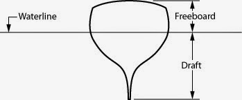
In sailing and boating, free board means the distance from the waterline to the upper deck level, measured at the lowest point of sheer where water can enter the boat or ship.

Freeboard defines the reserve bouyancy of a vessel. It is to be there to satisfy the reserve bouyancy regulations by IMO and other conventions. Reserve buoyancy is important for the vessel’s safe operation at sea.

Sufficient free board is required at all times to prevent the vessel being swamped and overwhelmed. For ocean going vessels, it is important to note that those structures above the waterline that are not watertight will not contribute to the reserve buoyancy of the vessel. Again, this makes sense – an open wheelhouse, or a cabin with the doors left open will not offer much protection if the vessel begins to ship water over the side.

Another factor affecting the freeboard to take into account is the trim of the vessel. Trim is defined as the difference between the draft forward and the draft aft. Draft is the depth of the hull below the water. If the aft draft is greater, the vessel is described as being trimmed by the stern, if the forward draft is greater, she is trimmed by the bow.

Length between perpendiculars and its Significance

Length between perpendiculars, often abbreviated as p/pp.p.ppLPPLBP or Length BPP is a term describing the length of a ship. LBP refers to the length of a vessel along the waterline from the forward surface of the stem, or main bow perpendicular member, to the after surface of the sternpost, or main stern perpendicular member. When there is no sternpost, the centerline axis of the rudder stock is used as the aft end of the length between perpendiculars.

Measuring to the stern post or rudder stock was believed to give a reasonable idea of the ship's carrying capacity, as it excluded the small, often unusable volume contained in her overhanging ends. On some types of vessels this is, for all practical purposes, a waterline measurement. In a ship with raked stems, naturally that length changes as the draught of the ship changes, therefore it is measured from a defined loaded condition.

The significance lies in the fact that this length gives the length of the waterline of the vessel, in loaded condition, a very crucial parameter.

Tuesday, April 21, 2015

Annex 1 discharge criteria outside special area and inside special area for marine vessels

Inside special areas or outside special areas within 50 nm


ANY DISCHARGE IS PROHIBITED with the exception of clean or segregated ballast

Outside Special areas: 


ANY DISCHARGE IS PROHIBITED, with the exception of clean or segregated ballast, or except when:

1. the tanker is proceeding en route, and

2. the instantaneous rate of discharge of oil does not exceed 30 litres/nm, and

3. the total quantity of oil discharged into the sea - does not exceed - for tankers delivered on or before 31 December 1979 - 1/15,000 of the total quantity of the particular cargo of which the residue formed a part - and - for tankers delivered after 31 December 1979 – 1/30,000 of the total quantity of the particular cargo of which the residue formed a part, and

4. the tanker has in operation an oil discharge monitoring and control system and a slop tank arrangement as required by regulations 29 and 31, respectively

Cylinder Head - Cylinder head mountings, Function and Combustion chamber shape.

Cylinder head or cylinder cover houses various fixtures called cylinder head mountings. They are positioned and designed very carefully, as they are subjected to very high combustion pressures, and temperatures. Cylinder head mountings and functions  are explained below in a brief sense.

Functions of cylinder head:

1. Forms a part of the combustion space- Cylinder head covers the top part of liner thus providing a space for combustion to take place. The shape of the cylinder head will greatly influence the combustion space shape, and thus characterstics and peak pressures developed in the engine. The efficiency of swirl and injection  also depends on the Shape of this space.the three main Combustion chamber designs are Hemispherical pent roof, Bath tub and Wedge.

2. Cylinder head mountings- It houses various running parts like Exhaust/inlet valves, Fuel injectors,  Relief valve,  Air starting valve, Rocker arm, indicator cock, cooling water and fuel connections etc.


How to test emergency generator?? how would you take it on load??

For emergency standby generators (required by life-safety code), critical loads supported by the generator system typically include emergency lighting, fire alarm systems, fire pumps, and elevators. Life-safety generators are also sometimes used to additionally support optional loads, such as data centers; however, in this case the life-safety loads take precedence over the optional loads.

1. Fuel tank fuel supply levels  piping, hoses and connectors; operating fuel pressure; and for any obstructions to tank vents and overflow piping.

2. Oil (check for proper oil level and oil operating pressure; lube oil heater) • Engine oil level can be checked with the unit stopped or running on many engines; otherwise, it should be checked with the unit stopped

3. Cooling system (check coolant level, water pump(s), jacket water heater, belts, hoses, fan)

4. Exhaust system (check drain condensate trap and for possible leakage)

5. Battery system [look for possible corrosion; check specific gravity, electrolyte level (a level between 1250 and 1275 is acceptable) and battery charger

 6. Electrical (conduct a general inspection of wiring and connections; check circuit breakers/fuses)

7. Prime Mover/Generator (Check for debris, foreign objects, loose or broken fittings; check guards and components; look for any unusual condition of vibration, leakage, noise, temperature or deterioration

 NOTE: This is not an all-inclusive list. The equipment manufacturer may have additional maintenance requirements that will likely include monthly, quarterly, semi-annual and annual inspections and checks.

Monthly testing

1. Emergency generators can be exercised monthly with the available load and exercised annually with supplemental loads at 25 percent of nameplate rating for 30 minutes, followed by 50 percent of nameplate rating for 30 minutes, followed by 75 percent of nameplate rating for 60 minutes, for a total of 2 continuous hours.

2. Load tests must include complete cold starts